|
| Menüeintrag |
|---|
| Draft -> Dimension |
| Arbeitsbereich |
| Draft, Arch |
| Standardtastenkürzel |
| D I |
| Siehe auch |
| FlipDimension |
Beschreibung
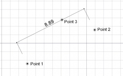
Das Bemaßungswerkzeug erstellt eine Bemaßung zwischen zwei Punkten im aktuellen Dokument. Die beiden Punkte legen den Abstand für die Bemaßung fest. Ein dritter Punkt legt die Maßlinie fest.
Verwendung
- Die Schaltfläche
 Draft-Dimension klicken oder die Tasten D und dann I betätigen.
 - Einen Punkt in der 3D-Ansicht anklicken oder eine Koordinate eingeben.
- Einen zweiten Punkt in der 3D-Ansicht anklicken oder eine Koordinate eingeben.
- Einen dritten Punkt in der 3D-Ansicht anklicken oder eine Koordinate eingeben.
Verfügbare Bemaßungsarten
- Lineare Bemaßungen: durch Auswählen von 2 Punkten oder einer Geraden, während die ALT-Taste gedrückt ist.
- Horizontale/vertikale Bemaßungen: durch Drücken der SHIFT-Taste, nachdem der erste Punkt ausgewählt wurde.
- Durchmesserbemaßung: durch Auswählen einer Kurvenlinie, während die ALT-Taste gedrückt ist.
- Radiusbemaßung: durch Auswählen einer Kurvenlinie, während die ALT-Taste gedrückt ist, und anschließend die SHIFT-Taste.
- Winkelbemaßung: durch Auswählen von 2 Geraden, während die ALT - Taste gedrückt ist.
Optionen
- Drücke die Taste X, Y oder Z nach einem Punkt um den nächsten Punkt auf die entsprechende Achse festzulegen.
- Um Koordinaten von Hand einzugeben, tippe einfach die Zahlen gefolgt von der ENTER zwischen der X-, Y- und Z-Komponente.
- Drücken von CTRL während des Zeichnens lässt snapping deinen Punkt bei der nächsten Rastposition einschnappen, unabhängig vom Abstand.
- Halten von SHIFT legt constrain die Maßlinie in horizontaler oder vertikaler Richtung fest oder wechselt zwischen Radius und Durchmesser,falls an einem Kreisbogen gearbeitet wird.
- Tippe auf R oder klicke in das Kontrollkästchen um den Relativ Modus ein- oder abzuschalten. Wenn der Relativmodus ausgewählt ist, sind die Koordinaten des nächsten Punktes relativ zum vorherigen Punkt. Ansonsten sind die Koordinaten absolute zum Ursprung (0,0,0) des Koordinatensystems.
- Press T or click the checkbox to check/uncheck the Continue button. If continue mode is on, you will be able to draw continued dimensions, one after the other, that share the same baseline.
- Press ESC or the Cancel button to abort the current Line command.
- By picking an existing edge with ALT, instead of entering measurement points, the dimension will become parametric and remember which edge it is bound to. If the endpoints of that edge move later on, the dimension will follow them.
- If an edge is selected before starting the Dimension command, the created dimension will also be parametric.
- The direction of the dimension can be changed afterwards, by modifying its "Direction" property
Properties
- DATAStart: The start point of the distance to measure
- DATAEnd: The end point of the distance to measure
- DATADimline: A point through which the dimension line must pass
- VIEWDisplay Mode: Specifies if the text is aligned to the dimension lines or always faces the camera
- VIEWFont Size: The size of the letters
- VIEWExt Lines: The size of the extension lines (between the measurement points and the dimension line)
- VIEWText Position: Can be used to force the text to be displayed at a certain position
- VIEWText Spacing: Specifies the space between the text and the dimension line
- VIEWOverride: Specifies a text to display instead of the measurement. Insert "$dim", inside that text, to display the measurement value
- VIEWFont Name: The font to use to draw the text. It can be a font name, such as "Arial", a default style such as "sans", "serif" or "mono", or a family such as "Arial,Helvetica,sans" or a name with a style such as "Arial:Bold". If the given font is not found on the system, a generic one is used instead.
- VIEWArrow Type: The type of arrow to use
- VIEWArrow Size: The size of the arrows
- VIEWDecimals: The number of decimal places to display on the dimension
- VIEWFlip Arrows: Reverse the orientation of arrows
- VIEWUnit Override: Expresses the distance in the given unit (leave blank to use the system unit) available in version 0.17
Scripting
The Dimension tool can by used in macros and from the python console by using the following functions:
makeDimension (p1,p2,[p3])
or
makeDimension (object,i1,i2,p3)
or
makeDimension (objlist,indices,p3)
- Creates a Dimension object with the dimension line passign through p3.
- The Dimension object takes the Draft linewidth and color set in the command bar.
- There are multiple ways to create a dimension, depending on the arguments you pass to it:
- (p1,p2,p3): creates a standard dimension from p1 to p2.
- (object,i1,i2,p3): creates a linked dimension to the given object, measuring the distance between its vertices indexed i1 and i2.
- (object,i1,mode,p3): creates a linked dimension to the given object, i1 is the index of the (curved) edge to measure, and mode is either "radius" or "diameter". Returns the newly created object.
makeAngularDimension (center,[angle1,angle2],p3)
- creates an angular Dimension from the given center, with the given list of angles, passing through p3.
- Returns the newly created object.
Beispiel:
import FreeCAD,Draft
p1 = FreeCAD.Vector(0,0,0)
p2 = FreeCAD.Vector(1,1,0)
p3 = FreeCAD.Vector(2,0,0)
Draft.makeDimension(p1,p2,p3)
