|
| Thema |
|---|
| Drafting |
| Niveau |
| Beginner |
| Zeit zum Abschluss |
| Autor |
| FreeCAD version |
| Beispieldatei(en) |
This tutorial will teach you how to use FreeCAD's 2D drafting module (also called Draft module) to create a simple architecture drawing. For this purpose, we will be drawing a simple masonry cabin. Let's assume that we received a CAD drawing showing the location of the cabin, and we'll use it to draw our project on top of it. We'll draw a plan, a section and two elevations.
Before you begin
Keep in mind that FreeCAD is still in an early stage of development, so you might not be as productive as with another CAD application, and you will certainly encounter bugs, or experience crashes. FreeCAD now has the ability to save backup files. The number of those backup files can be specified in the preferences dialog. Don't hesitate to allow 2 or 3 backup files until you know well how to deal with FreeCAD.
Save your work often, from time to time save your work under a different name, so you have a "safe" copy to fall back to, and be prepared to the possibilty that some commands might not give you the expected results.
Setting up your FreeCAD workspace
FreeCAD is a 3D modeler, but in this tutorial we will use it only for working in 2D. So, we will be drawing on the ground plane, and everything we do will have a Z coordinate of zero. So first, let's put ourselves in top view by pressing the 2 and be sure we are in orthographic projection (key O) otherwise we might get fooled by some perspective effects.
Another very important thing to do, is to give custom hotkeys to your Draft commands. So you can do all the commands from the keyboard, which will drastically improve your speed. Basically you can do about everything from the keyboard, and will need the mouse only to draw points and select objects. Go to menu Customize -> Keyboard -> Category Python and select shortcuts as you like, a good idea is to make them easy to remember. For example, I use L for Line, W for Polyline (also called Wire in FreeCAD), A for Arc, C for Circle, M for Move, R for Rotate, F for Offset (O is already taken by Orthographic), D for Dimension, T for Text, etc...
Now we are set up, we can begin to draw.
Importing CAD drawings
If you are going to import a 2D cad drawing, chances are high that they will be in a proprietary format such as .dwg (from AutoCAD) or .mcd (from VectorWorks). The specification of those file formats are being kept secret by their vendors, so it is extremely difficult or totally impossible for FreeCAD to support them. However, One file format that is fairly well documented is the DXF format, and the Draft module supports it partially.
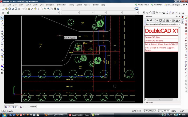
Almost all CAD applications can export to the DXF format, and you also have several free converters such as openDWG's "Teigha file Converter" utility, that will allow you to convert your file to the DXF format. For example, Doublecad is a free, fully functional CAD program that allows you to export DXF files:
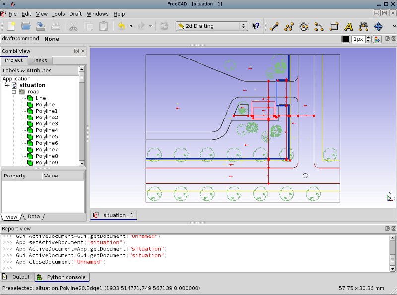
Open your DXF file simply with the File -> Open dialog. Several import settings can be configured in the Draft Preferences screen. For example, you can configure if you want the DXF file to be imported with original colors and linewidths, or converted to current Draft color, that you see at the right side of the Draft command bar. But in FreeCAD you won't need to attribute ugly colors to your objects to determine their linewidth. Objects all have independent color and linewidth attributes. So, you can very well forget about DXF colors, or convert everything to the colors of your choice.
After importing your drawing in FreeCAD, it will look like this:
Let's begin with doing some cleaning.
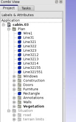
In FreeCAD, there are no layers like in AutoCAD. We work with groups instead. Groups are another more flexible way to organize your drawing. You can create new groups with a right-click on the tree view, rearrange them, move them into other groups, or move objects to/from groups simply by dragging and dropping things in the tree view. You can also assign current line width and colors to all objects in a group, or turn them on or off by pressing SPACE.Let's put all our objects into one new group, and turn off everything we won't use, like vegetation and dimensions, to speed up our work.
Drawing the plan view
Using the drawing tools
The only thing we'll need at the moment is the area that is assigned to our cabin. It lies in a separate group named "projection". So we can basically turn off everything else with the SPACE key, and start drawing on top of it. We will draw a small cabin with a guard room and a WC, in very simple structural masonry, so there won't be any need for special concretework in the plan itself. But we'll put a layer of plaster inside, and a layer of ceramics outside.
So, let's begin with doing the general shape of our walls:
Our DXF drawing was drawn in meters, so unless we have any reason to change that, we'll continue with the same units. FreeCAD currently does not have a friendly system to work with real-world units, so we simply assume that "one" means "one meter".
Another good thing to remember is to construct temporary geometry whenever you need. You want a point that lies 2 meters away horizontally? Draw a vertical line, move it 2m away, pass a horizontal line through it, there is your point.
- Create a rectangle: Snap its cornerpoints with CTRL to the corners of the assigned area
- Offset the rectangle: With the rectangle selected, press Offset, press C to turn on copy mode, move your mouse inside the first rectangle so offset knows in which direction to go, and type 0.20, Enter
- Turn them into a face: Upgrade the first rectangle, upgrade the second rectangle, then select the outer rectangle, CTRL-select the inner rectangle and press Downgrade
- Create the door opening: Make a 1.00 x 0.50 rectangle, move it to the upper corner of our main wall (press C to turn copy mode off).
- Move the door opening to the right position: Move it 0.10 to the left. We won't put our opening directly on the corner, because it would make the door difficult to open.
- Subtract the door opening: Select the wall, CTRL-select the door opening, and press downgrade.
A note about upgrade & downgrade
Now, you must be aware that the openCasCade kernel that FreeCAD is built upon, is a 3D kernel. It is made primarily for 3D operations. When it has to cut or unite planar faces, like we are doing now with upgrade/downgrade operations, it sometimes does strange things, and subsequent operations (like other upgrades/downgrades) sometimes don't give the expected results. Of course with time those behaviours will end up being corrected by the FreeCAD developers, but it is wise to know alternative ways to solve immediate problems.
The best way to solve a face that isn't upgrading/downgrading/offsetting correctly, is simply to downgrade it until it is all exploded to single edges, then upgrade those edges together again up to a new face. In case that doesn't work either, simply redraw a new wire (polyline) on top of the problematic face, snapping to its endpoints, then delete the old face and upgrade the new wire. Usually a face that you draw yourself is in much better shape than a face that you obtained by upgrade/downgrade.
Another thing to keep in mind is that when you subtract a shape from another, you can find yourself with one object containing several faces. This might difficult your further work (they don't offset correctly, etc), so a good thing in that case is always to separate them with the downgrade tool.
Another note about snapping
There are two forms of snapping in the Draft module: passive snap, which occurs when you simply pass your mouse cursor over an object (an open circle symbol appears), and active snap, which is when you press CTRL. Active snapping allows you to snap to specific points on an object, like its endpoints, midpoints, centers, or intersections with other objects. If you press SHIFT, which is the key for constraining horizontally and vertically, you gain even more snapping points. But this has a cost, because FreeCAD must do many calculations in real time. If you have many objects, you'll begin to feel the difference. So a good trick to speedup your work is to take the habit of working as much as possible with SHIFT and passive snapping only. You will see quickly that you'll obtain accurate results and work much faster.
So let's go back to work:
- Create a 10cm-wide wall between the main room and the WC. Upgrade it, then upgrade it together with the main wall to unite them
- Create other rectangles for your other openings. I put a 60cm-wide window in what will become the WC, a 80cm door between the main room and the WC, and for the big window in the main room I simply left 40cm wall at the left and right side.
- Offset all the walls of 1cm, to make a cement/plaster layer, then downgrade the offsetted copies to turn them into simple wires
- Create a layer of ceramics on the exterior side, by offsetting our plaster line 2cm, then drawing a 2cm-thick shape between the two lines
- Delete the 2cm offset. that we don't need anymore, as well as all construction geometry. If you feel you might need them later, simply put them in a separate group and turn that group off with SPACE.
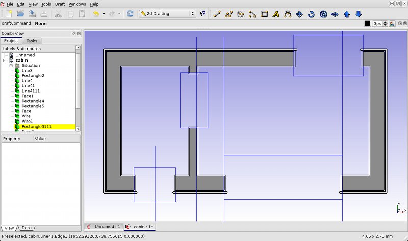
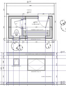
This is where we are now (I kept construction geometry there, in blue, for you to see):
Importing and building compound objects
In FreeCAD, compound objects are objects made with the geometry of several other objects. In other softwares, it is called blocks, symbols or components. It is a very handy way to group geometry under one single object. Any of the objects created with the draft module can be grouped into a compound. The command to create a compound is the Upgrade command. The use is simple, select everything you want to turn into a compound, and press Upgrade. If no other more intelligent shape can be created, they will be turned into a compound.
Using compound geometry is specially useful to build a symbol library on your disk, so you can reuse them later. One cool use of this, coupled to the DXF import function, is that you can very easily use symbol libraries in DXF format (if your symbols are in dwg format, the free "Teigha file Converter" application can batch-convert all your library at once).
Once you have a library of DXF symbols, just drag one of them and drop it on top of your open FreeCAD window and it will be imported in the current document. It won't be imported as a compound, but all of the symbol geometry will be placed in a separate group, so it is easy to select it all and simply press "Upgrade". Beware that AutoCAD users have the bad habit of drawing things very far from the origin point (0,0,0), your inserted symbol can then lie very far from your drawing zone.
So, back to our drawing:
- Import a sanitary block if you have one, or pick one on the Cad Exchange site, and convert it to DXF with the "Teigha file Converter"
- Create the geometry for a door, upgrade it to a compound, copy it to the other door location, downgrade it, adjust the elements to the new size, and upgrade it again
- Do the same for the windows
Dimensions and annotations
Now that our plan is more or less ready, we can add dimensions and texts. This is usually pretty straightforward, so there is probably no need to explain much. Just try to dimension everything, and as a convention, always start the dimension lines from the main wall line, not the finishing layer. One thing is good to know, sometimes you draw a text or a dimension over a filled area, and the filled area will cover your dimension. There is a simple way to fix that, it is by downgrading and upgrading again the filled area. It will then be displayed under the other elements.
The dimension and text will by default have the same text height, which can be changed in the Draft Preferences page. You can then edit individually each text height.
Unfortunately certain non-geometry objects like texts and dimension are still not selectable in the FreeCAD 3D view, you must therefore select them in the tree, and you won't be able to snap to them, but this will probably be solved in a near future. It is also not possible at the moment to choose a font style. To align dimensions, at the moment, you need to draw a line first, then snap your dimensions to that line.
Organizing
Finally, we can add a few things to finish our plan, like putting vegetation around the cabin. We can simply copy a few trees from our imported DXF drawing and scale them down with the scale tool, to for example (0.5,0.5). We can also change the line thickness of a couple of objects, for example make the walls thicker, and change the color of some things. And we can organize all our elements in groups.
The ability to organize your work in nested groups is surely one of the big advantages of groups over traditional work with layers. In this tutorial, I grouped my objects by type, inside the Plan group. For example, instead of having one big layer with all dimensions of your drawing, each part of the drawing will contain their own dimensions group, making it extremely easy to organize your drawing.
You might feel a loss at first if you come from a traditional drawing program like AutoCAD, but you'll quickly see the power that this method brings.
For example, all our construction geometry can go in a separate group, that we'll turn off. Maybe later we'll need to make some changes, and it will be handy to have that geometry available.
So, now we are ready to draw other parts...
Drawing the elevations
Since in this exercise we are going to stay in pure 2D, we will draw our elevations and sections directly. In more advanced architecture environments (what FreeCAD will hopefully become in some future), we wouldn't need to draw the elevations. We would model the building in 3D and then generate the different views automatically. But for the sake of this exercise (and also because all the needed tools are still not implemented in FreeCAD), we'll do it by hand, like in the old times.
We'll begin with the rear wall elevation, because the way our plan is oriented, it can be drawn directly below it, without the need to rotate the view. We will simply draw construction lines from the plan, set horizontal lines to the desired heights, I set the 0.00 level, the +0.15 level of the slab, then heights for the windows, and the roof slab at +2.50. We can then draw our geometry very quickly on top of it.
We can then place a couple of annotations, dimensions, and upgrade some of the objects so they appear filled with a color. Finally, we can make a bit of cleaning by creating a "South Elevation" group, then subgroups for our construction geometry and annotations, and place all of our new objects in them.
Rotating the view, and creating macros
Now, we need to draw other elevations of our little building. The simplest way would be to draw them directly under the plan view, as we did with the south elevation. For this, it would be handy to be able to rotate the view by 90°, so we can continue drawing our elevations "on foot". Unfortunately, FreeCAD has at the moment no "Rotate View" tool. But, fortunately, it has tools for us to easily create our own tools, called Macros. So, this is a good opportunity for us to try something easy.
Macros, as well as all scripting in FreeCAD, is done in a very simple programming language called python. You can write very complex programs in FreeCAD in python, but you can also use it to perform very simple operations where there still isn't a proper FreeCAD toolbar icon, such as our Rotate The View tool. So, first thing to do, open the Report view, if you closed it, and select the python tab. In there, type (or copy/paste) the following code:
import math
 from pivy import coin
 cam = Gui.ActiveDocument.ActiveView.getCameraNode()
 rot = coin.SbRotation()
 rot.setValue(coin.SbVec3f(0,0,1),math.pi/2)
 cam.orientation = rot
This small script will simply rotate the view by 90° (left). For rotating by -90° (right), you would simply change math.pi/2 by -math.pi/2. If you would like to learn more about python scripting in FreeCAD, there is an extensive Scripting section on this wiki.
Now, we need to do one more step, which is save our piece of code in a macro, so we can reuse it later. So, instead of pasting our code in the python interpreter, let's open the macro manager (Tools -> Macros), create a new macro, press the "Edit" button and paste our code in it. Close the macro editor tab, and the macro will be saved.
The macros can behave like any other FreeCAD tool. With the Tools -> Customize menu, we can add an icon to our macro, a keyboard shortcut, and add it to a toolbar.
Drawing the rotated views
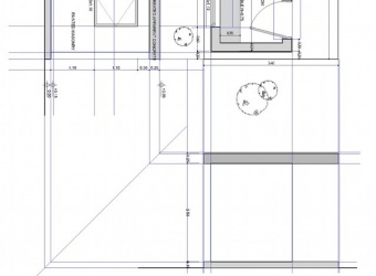
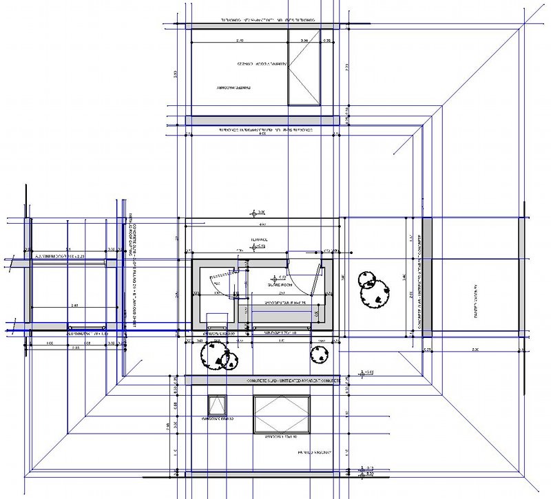
Now that we can rotate the view at will, we can draw our other elevations. The easiest way is to draw your elevation at the right place under the plan view, and use a "mirror" (a 45°-oriented line) to push the height lines from another elevation. This way, drawing goes pretty fast.
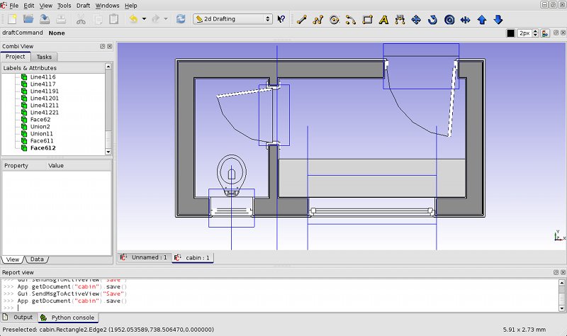
Finally, we draw 2 others elevations, and since the fourth one is the same as the second one (but mirrored), we will skip it. We can then draw a cross section, and our drawing is complete:
To be continued...
