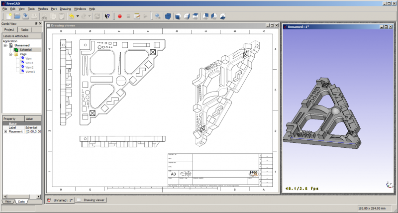
ドローイングモジュールを使うと3D作業物を紙の上に移すことができます。つまりモデルのビューを2Dウィンドウに表示し、図面にそのウィンドウを挿入するということです。例えば枠線、タイトル、ロゴマークが入ったシートに挿入し、最終的にそのシートを印刷することができます。ドローイングモジュールは現在も製作中で多かれ少なかれ技術面でのテスト段階にあります!
GUIツール
This template is now obsolete and is directly include in the original page
2D図面を作成、設定、エキスポートするためのツールです。
-
 スケーラブルベクターグラフィックを開く: SVGファイルとして保存されている図面を開きます
 -
 A3図面の新規作成: FreeCADのデフォルトのA3テンプレートから新しい図面を作成します
 -
 ビューの挿入: アクティブな図面上に選択されたオブジェクトのビューを挿入します
 -
 図面の保存: 現在の図面をSVGファイルとして保存します
この画像を見るとドローイングモジュールの主要なコンセプトが見て取れます。ドキュメントには図面に引用したい形状オブジェクト(Schenkel)が入っています。さらに"Page"が作成されています。ページはテンプレートに基づいてインスタンス化されます。今回のケースでは"A3_Landscape"テンプレートです。テンプレートにはSVGドキュメントであなたが普段使っているページ枠、ロゴ、標準のプレゼンテーション資料規格を使うことができます。
このページには複数のビューを挿入することができます。各ビューはページ上での位置(X、Yプロパティ)、拡大率(スケールプロパティ)などをはじめとした属性情報を持っています。ページ、ビュー、参照しているオブジェクトが変化するとそのたびにページが再生成され、ページの表示が更新されます。
スクリプト処理
今のところエンドユーザー用の(GUI)ワークフローは非常に限定されたものしか用意されていません。APIはもっと充実しています。以下ではドローイングモジュールのスクリプト処理用APIをどう使うかの例を挙げていきます。
簡単な例
まずはパートモジュールとドローイングモジュールが必要です。
import FreeCAD, Part, Drawing
小さなサンプルパーツを作成します。
Part.show(Part.makeBox(100,100,100).cut(Part.makeCylinder(80,100)).cut(Part.makeBox(90,40,100)).cut(Part.makeBox(20,85,100)))
投影させます。G0はシャープな輪郭線、G1は連続線を意味します。
Shape = App.ActiveDocument.Shape.Shape
[visibleG0,visibleG1,hiddenG0,hiddenG1] = Drawing.project(Shape)
print "visible edges:", len(visibleG0.Edges)
print "hidden edges:", len(hiddenG0.Edges)
全てZ平面に投影されます。
print "Bnd Box shape: X=",Shape.BoundBox.XLength," Y=",Shape.BoundBox.YLength," Z=",Shape.BoundBox.ZLength
print "Bnd Box project: X=",visibleG0.BoundBox.XLength," Y=",visibleG0.BoundBox.YLength," Z=",visibleG0.BoundBox.ZLength
異なる投影ベクトル。
[visibleG0,visibleG1,hiddenG0,hiddenG1] = Drawing.project(Shape,App.Vector(1,1,1))
SVGに投影。
resultSVG = Drawing.projectToSVG(Shape,App.Vector(1,1,1))
print resultSVG
パラメトリックな方法
物体を作成します。
# 直方体を三つ、円筒を一つ作成
App.ActiveDocument.addObject("Part::Box","Box")
App.ActiveDocument.Box.Length=100.00
App.ActiveDocument.Box.Width=100.00
App.ActiveDocument.Box.Height=100.00

App.ActiveDocument.addObject("Part::Box","Box1")
App.ActiveDocument.Box1.Length=90.00
App.ActiveDocument.Box1.Width=40.00
App.ActiveDocument.Box1.Height=100.00

App.ActiveDocument.addObject("Part::Box","Box2")
App.ActiveDocument.Box2.Length=20.00
App.ActiveDocument.Box2.Width=85.00
App.ActiveDocument.Box2.Height=100.00

App.ActiveDocument.addObject("Part::Cylinder","Cylinder")
App.ActiveDocument.Cylinder.Radius=80.00
App.ActiveDocument.Cylinder.Height=100.00
App.ActiveDocument.Cylinder.Angle=360.00
# 二つの直方体と円筒を結合
App.activeDocument().addObject("Part::Fuse","Fusion")
App.activeDocument().Fusion.Base = App.activeDocument().Cylinder
App.activeDocument().Fusion.Tool = App.activeDocument().Box1

App.activeDocument().addObject("Part::Fuse","Fusion1")
App.activeDocument().Fusion1.Base = App.activeDocument().Box2
App.activeDocument().Fusion1.Tool = App.activeDocument().Fusion
# 一つ目の直方体で結合した形状を切断
App.activeDocument().addObject("Part::Cut","Shape")
App.activeDocument().Shape.Base = App.activeDocument().Box
App.activeDocument().Shape.Tool = App.activeDocument().Fusion1
# 作業した形状を全て非表示にする
Gui.activeDocument().Box.Visibility=False
Gui.activeDocument().Box1.Visibility=False
Gui.activeDocument().Box2.Visibility=False
Gui.activeDocument().Cylinder.Visibility=False
Gui.activeDocument().Fusion.Visibility=False
Gui.activeDocument().Fusion1.Visibility=False
Pageオブジェクトを挿入し、テンプレートを代入
App.activeDocument().addObject('Drawing::FeaturePage','Page')
App.activeDocument().Page.Template = App.getResourceDir()+'Mod/Drawing/Templates/A3_Landscape.svg'
"Shape"オブジェクトのビューを作成。位置とサイズを定義してPageに代入
App.activeDocument().addObject('Drawing::FeatureViewPart','View')
App.activeDocument().View.Source = App.activeDocument().Shape
App.activeDocument().View.Direction = (0.0,0.0,1.0)
App.activeDocument().View.X = 10.0
App.activeDocument().View.Y = 10.0
App.activeDocument().Page.addObject(App.activeDocument().View)
同じオブジェクトに対して二つ目のビューを作成。ただし今回のビューは90度回転させます。
App.activeDocument().addObject('Drawing::FeatureViewPart','ViewRot')
App.activeDocument().ViewRot.Source = App.activeDocument().Shape
App.activeDocument().ViewRot.Direction = (0.0,0.0,1.0)
App.activeDocument().ViewRot.X = 290.0
App.activeDocument().ViewRot.Y = 30.0
App.activeDocument().ViewRot.Scale = 1.0
App.activeDocument().ViewRot.Rotation = 90.0
App.activeDocument().Page.addObject(App.activeDocument().ViewRot)
同じオブジェクトに対して三つ目のビューを作成。ただし等角図の方向を使用します。また隠れている線も表示させます。
App.activeDocument().addObject('Drawing::FeatureViewPart','ViewIso')
App.activeDocument().ViewIso.Source = App.activeDocument().Shape
App.activeDocument().ViewIso.Direction = (1.0,1.0,1.0)
App.activeDocument().ViewIso.X = 335.0
App.activeDocument().ViewIso.Y = 140.0
App.activeDocument().ViewIso.ShowHiddenLines = True
App.activeDocument().Page.addObject(App.activeDocument().ViewIso)
適当に何か変更して更新。更新処理によってビューとページが変化します。
App.activeDocument().View.X = 30.0
App.activeDocument().View.Y = 30.0
App.activeDocument().View.Scale = 1.5
App.activeDocument().recompute()
こまごまとした物へのアクセス
一つのビューからSVGの図を取得。
ViewSVG = App.activeDocument().View.ViewResult
print ViewSVG
結果ページ全体を取得(ドキュメントのテンポラリフォルダ内の読み取り専用ファイル)。
print "Resulting SVG document: ",App.activeDocument().Page.PageResult
file = open(App.activeDocument().Page.PageResult,"r")
print "Result page is ",len(file.readlines())," lines long"
重要:ファイルを解放!
del file
独自のコンテンツを使用してビューを挿入。
App.activeDocument().addObject('Drawing::FeatureView','ViewSelf')
App.activeDocument().ViewSelf.ViewResult = """<g id="ViewSelf"
  stroke="rgb(0, 0, 0)"
  stroke-width="0.35"
  stroke-linecap="butt"
  stroke-linejoin="miter"
  transform="translate(30,30)"
  fill="#00cc00"
  >

  <ellipse cx="40" cy="40" rx="30" ry="15"/>
  </g>
"""
App.activeDocument().Page.addObject(App.activeDocument().ViewSelf)
App.activeDocument().recompute()

del Shape,ViewSVG, resultSVG
以下のような結果になります:
テンプレート
FreeCADには一通りのデフォルトテンプレートが付属していますがドローイングテンプレートにはもっと多くのテンプレートがあります。

