|
| Beschreibung |
|---|
| Creates an image 3D from a BMP image. |
| Autor |
| Mario52 |
| Link |
| Liste von Macros How to install macros How to customize toolbars |
| Version |
| 0.10 |
| Datum zuletzt geändert |
| 2016-12-28 |
Description
This small macro allows you to build a project 3D very easily from a bitmap image 256 levels of gray.
I hope that this macro will revolutionize the way of thinking the CAD and CNC any image when what can be converted to object 3D without any intervention.
Everything becomes possible regardless of the complexity of the image !
The macro Macro Loft for automate the multi loft
Use
This macro need an image in 256 gray levels (0-255) therefore before using the macro, convert your image into grayscale (black and white) Lowe. The number of colors is detected automatically, if the image is more than 256 colors another function is expected (to come). Each color (gray level) is regarded as a deep, white (255) the level high and black (0) the lowest level (deep).
Configuration is done before the opening of the file, default values are the settings provided to get a project's dimensions:
- width of the image in points in the coordinate X,
- height of the image in points in the coordinate Y,
- depth or thickness of the project leaked 10 mm (in raw mode, on 256 mm) in the coordinate Z.
The image file unfolds like a scanner x1 x2 x3 ... in 1 mm increments in FreeCAD similarly to the value y of 1 mm at a time. The value of z is given by the value of the color. These values are configurable in the macro.
Attention: depending on the size of the image, the project can become very big! for the record an image of 100 px wide and 100 px in height gives 100 x 100 = 10000 points 'and as each point corresponds to a coordinate, so 10000 coordinates XYZ there.
The interface
- Coordinate
- Coordinate X: X coordinate of position of the object, default: 0.
- Coordinate Y: Y coordinate of position of the object, default: 0.
- Coordinate Z: coordinate Z position of the object, default: 0.
- Stetching
- Stetching X: narrowing or enlargement of the length of the object, default: 0.
- Stetching Y: narrowing or enlargement of the height of the object, default: 0.
- Stetching Z: narrowing or enlargement of the depth of the object, default: 0.
- Inversion
- Inversion X: reverse coordinates X image.
- Inversion Y: reverse coordinates Y image.
- Inversion Z: reverse coordinates Z image.
- Mode 8 Bits
The beginning of the operation value automatically adapts to the selected function: 0 if the setting is on black (Black) 255 or 20 if the setting is white (White).
- Wire: build your line (vector) in the form of Wire.
- Bspline: build your line (vector) in the form of Bspline.
- Cloud build the points vectors in the points cloud.
- Point: creates a point at each pixel (vector). (the procedure can be long)
- Nuance: If the shade option is checked the color of the point is represented as a picture.
- Mode 32 Bits
- Photo: the photo mode is automatically activated when a 32-bit image is detected. (the procedure can be long)
- Plan: the plan allows you to import a 32-bit image and ignore the background of the plan. By default the map background is black to ignore colors are adjustable with the Capping command. If White is checked, the bottom has ignore will be white. (the procedure can be long)
- Files
- pcd: if is checked one file originalName.bmp.pcd is saved in the same directory of the file (pcd v0.7).
- asc: if is checked one file originalName.bmp.asc is saved in the same directory of the file. This file can be used as a cloud point (format: X Y Z).
- Capping (10mm)
- Slider: give the height of the form the height is displayed on title frame.
- Raw mode: to adjust the number of colors (depth). The default mode is 0-20 (which constitutes a filter and to obtain more details according to the complexity of the image) once the checked the mode is 0 to 255 (the entire range of colors).
- CheckBox: this checkBox enabled the spinbox.
- SpinBox: this spinbox give the contour line do not use (ex: 0 for the base).
- Capping: the capping function can be made on the choice of colours, white (default) or black. The degrees of capping rule 20 to 0 (or 255 to 0) if the checkbox is set on W (unchecked) or 0 to 20 (or 0 to 255) if the checkbox is set on B (checked).
- SpinBox: this spinbox give the degrees of capping.
- File and lauch: opens the image file and launches the conversion.
- Quit: exits the function.
Script
Macro_Texture.FCMacro
Download the macro to Gist Macro FCTexture.FCMacro
Example
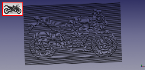
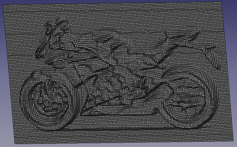
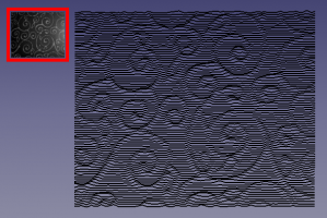
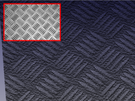
The images were inclined to enhance the 3D effect.
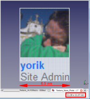
Here an example of a bmp image converted to points and restoring picture the width of the image is 6.5 nm
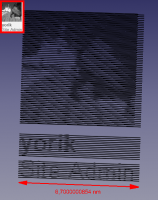
thanks for the permission of YorikHere an example of a bmp image converted to object 3D of 6.7 nm width.
thanks for the permission of Yorik
A portion of the screen FreeCAD. The file.
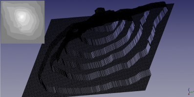
Mode Plan: the image on the left the white background has been ignored in the right image the colour black has been ignored (an example on the forum)
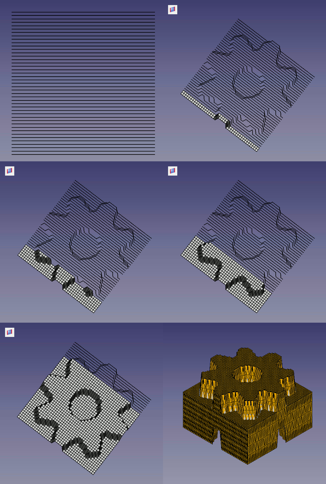
Procedure for create solid:
1: Create loft with thetools or with the Macro Loft
2: Select all and extrude with the tools
3A: For Linux Download GMSHMesh (author psicofil) Macro_GMSH Wiki page
3B: For Windows Download GmshMesh2.zip unzip the file and install it in your Mod directory (author ulrich1a)
4: Create your Mesh file and use it
Convert solid in mesh with GmshMesh.
Links
The discussion on the forum to give your impressions or contact me.
The macro Macro Loft for automate the multi loft
How to handle pdf import properly and feasibly?
Revision
- ver 0.10 : 28/12/2016 add save point in .pcd, .asc display a points cloud, height form, contour
- ver 0.9 : 12/12/2016 adding save file .asc for cloud point
- ver 0.8 : 16/03/2016 adding progressBar
- ver 0.7 : 03/09/2014 Delete "translate" forgotten and bug fix discovered by the passage of PyQt to Pyside !
- ver 0.6 : 26/08/2014 Delete all "_translate"
- ver 0.5 : 25/08/2014 Delete "_translate (" MainWindow "," Stretching X ", None)" that prevented the display of tooltip with PySide (Windows Vista)
- ver 0.4 : 08/08/2014 PyQt4 PySide
- ver 0.3 : 28/03/2014 :comment out the line "# self.checkBox_5.setAccessibleName(_fromUtf8(""))"
that causes an error with the version FreeCAD : Version: 0.14.3343 (Git), Python version: 2.7.6, Qt version: 4.8.5
