Description
Cet utilitaire permet de créer des points (Centre de lignes, centre de cercle, centre d'objet...),
Des Axes (à partir de 2 points, Normal à un Plan...),
des Plans (à partir de 3 points, à partir d'un axe et d'un point...)
Et d'autres petits utilitaires pour faciliter la creation de votre projet FreeCAD.
Cet utilitaire s'affiche dans la vue combinée.
Utilisation
Work Features
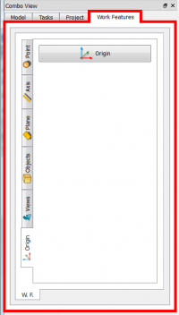
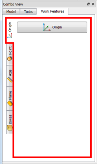
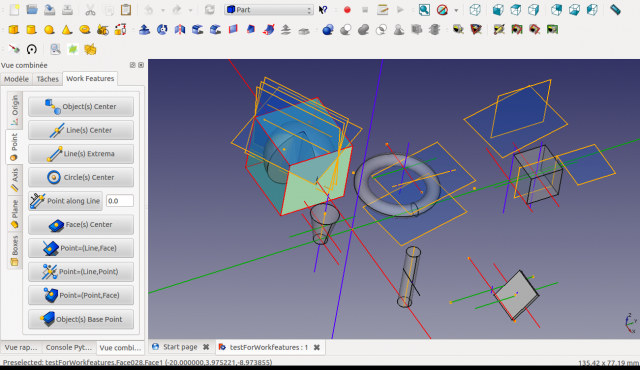
Après l'activation de Work Features, l'outil créé un nouvel onglet dans la vue combinée.
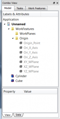
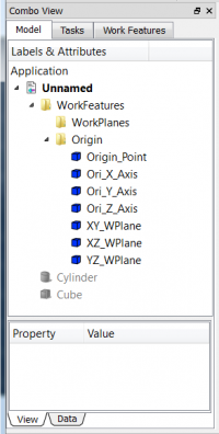
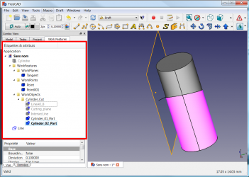
La création de work features ajoute des éléments correspondants dans l'arborescence Modèle, classés sous un groupe « WorkFeatures ». Les axes, point et plans d'origine sont automatiquement cachés.
Les commandes usuelles permettent de basculer la visibilité des fonctions créées.
Par ex. sélectionnez votre objet et appuyez sur Space ou faites un clic droit et choisissez "Afficher la sélection" ou "Masquer la sélection".
Onglet Origin
|
|
- Onglet Origin
- Origin : Créer à l'origine : un point et l'axe X, Y ou Z ou les plans XZ, XY et YZ. Les axes, point et plans d'origine sont automatiquement cachés.
|
Onglet Points
|
|
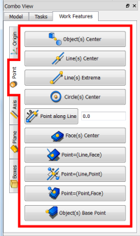
- Onglet Points
- Object(s) Center : Créé un point au centre des objets sélectionnés.
- Lines(s) Center : Créé un point au milieu de chaque ligne sélectionnée.
- Line(s) Extrema : Créé un point aux extrémités de chaque ligne sélectionnée.
- Circle(s) Center : Crée un point au centre du cercle(s) ou d'arc(s) sélectionné(s).
- Point along Line : Créé un point sur la ligne à une certaine distance du point d'extrémité sélectionné.
- Case de saisie : saisir une valeur de déplacement.
- Face(s) Center : Créé un point au centre de chacune des faces sélectionnées.
- Point (Line,Face) : Créé un point à l'intersection de la ligne et du plan sélectionnés.
- Point (Line,Point) : Crée une projection d'un point sur un point ou un point symétrique.
- Point (Point,Face) : Projeter un point sur une face.
- Object(s) Base Point : Créer un point de base sur tous les objets sélectionnés.
|
Onglet Axis
|
|
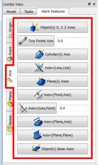
- Onglet Axis
- Object(s) X, Y, Z Axes : Créé 3 axes au centre de tous les objets sélectionnés.
- Two Points Axis : Créé un axe traversant deux points.
- Case de saisie : saisir la valeur de déplacement.
- Cylinder(s) Axis : Créé un axe au centre d'un cylindre.
- Axis (Line,Line) : Créé un axe entre deux axes.
- Plane(s) Axes : Créé deux axes perpendiculaires au centre d'un plan.
- Axis (Point,Axis) : Créé un axe parallèle à un autre axe et croisant un point.
- Axis (Axis,Point) : Créé un axe perpendiculaire à un autre axe et croisant un point.
- Case de saisie : saisir la valeur de déplacement.
- Axis (Plane,Axis) : Projette un axe sur un plan.
- Axis (Plane,Plane) : Créé un axe à l'intersection de deux plans.
- Object(s) Base Axis : Créé 3 axes à l'emplacement de base des objets sélectionnés.
|
Onglet Plane
|
|
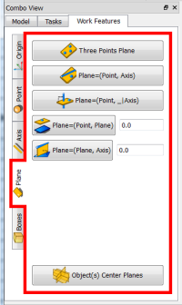
- Onglet Plane
- Three Points Plane : Créé un plan croisant 3 points.
- Plane (Point, Axis) : Créé un plan croisant une ligne et un point. Le point ne doit PAS appartenir à la ligne !
- Plane (Point, _Axis) : Créé un plan perpendiculaire à une ligne et croisant un point.
- Plane (Point, Plane) : Créé un plan croisant un point et parallèle à un plan.
- Case de saisie : saisir la valeur de déplacement.
- Plane (Plane, Axis) : Créé un plan croisant une ligne et perpendiculaire à un plan.
- Case de saisie : saisir la valeur de déplacement.
- Object(s) Center Planes : Créé 3 plans (XY, XZ et YZ) au centre des objets sélectionnés.
|
Onglet Boxes
|
|
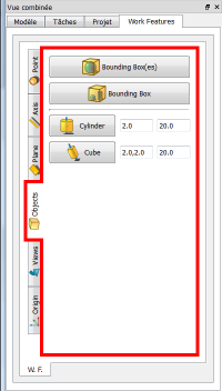
- Onglet Boxes
- Bounding Box(es) : Créé des boîtes englobantes autour de chacun des objets sélectionnés.
- Bounding Box : Créé une boîte englobante autour de chacun des objets sélectionnés.
- Cylinder : Sélectionnez d'abord un axe et un point. Définissez le diamètre et la longueur si nécessaire. Cliquez ensuite sur le bouton ... Il va créer un cylindre aligné sur l'axe sélectionné, avec une des extrémités au point sélectionné.
- Cube : Sélectionnez d'abord un axe et un point. Définissez les dimensions si nécessaire. Cliquez ensuite sur le bouton ... Il va créer un Cube aligné sur l'axe sélectionné. avec l'une des extrémités au point sélectionné.
|
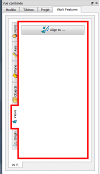
Views Tab
|
|
- Views Tab
- Align to ... : Défini la vue en cours perpendiculairement à la face sélectionnée, ou aligné sur l'axe sélectionné, ou alignés sur les deux points. Cliquer à nouveau avec la même sélection, renversera la direction.
|
Modif. Tab
|
|
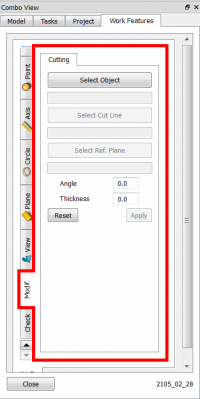
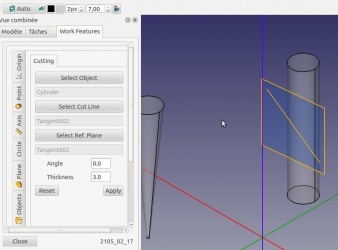
- Modif. Cutting Tab
- Select Object : After selected your object and, First, one Object to cut and click 'Select Object' button,
- The name of the object selected are displayed
- Select Cut Line : Second, one cutting Line and click 'Select Cut Line' button,
- The name of the line selected are displayed
- Select Ref. Plane : Last, a reference Plane and click 'Select Ref. Plane' button!
- The name of the plane selected are displayed
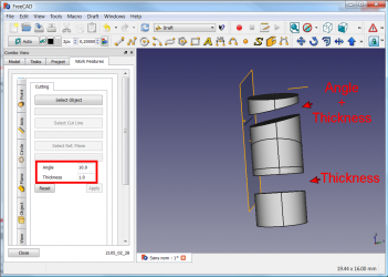
- Angle : Angle for cut (Defaut : 0.0)
- Thichness : Thichness the cut (Defaut : 0.0)
- Reset : Reset the values
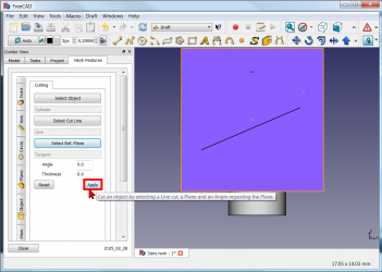
- Apply : Apply the values
|
Check. Tab
|
|
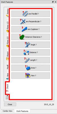
- Check. Tab
- are Parallel ? : Check if two faces or two Edges are Parallel:
- Select the 2 faces/planes or 2 Edges/Lines and Click this button
- are Perpendicular ? : Check if two faces or two Edges are Perpendicular:
- Select the 2 faces/planes or 2 Edges/Lines and Click this button
- are Coplanar ? : Check if two faces or two Edges are Coplanar:
- Select the 2 faces/planes or 2 Edges/Lines and Click this button
- Distance Clearance ? : Check for two Objects Clearance distance:
- Quick measurements between parallel faces and similarly placed objects Select the 2 Objects and Click this button
- Angle ? : Calculate angle from 2 objects:
- Angle measurement between two Edges or two Planes
- Select the 2 Edges and Click this button
- or : Select the 2 Planes and Click this button
- or : Select one Edge and one Plane and Click this button
- Distance ? : Check for two Points distance:
- Distances measurement and Delta values (on main Axes) between two Points
- Select the 2 Points and Click this button
- Length ? : Check for Line Length:
- Length measurement and Delta values (on main Axes) for a Line
- Select the Line and Click this button
- Area ? : Check for surface Area:
- Area measurement for a Plane or a set of Planes.
- Select One or several Planes and Click this button
- View : Detect the position of the camera. The returned value is the value provided by the function getCameraOrientation().
|
Script
Après téléchargement du fichier compressé ici
Download the latest version on GitHub ,
Vous devez décompresser l'archive zip et copier tous les fichiers dans votre répertoire Macro.
PS:Cette macro est toujours en développement vérifiez de temps en temps pour vous assurer d'avoir la dernière version.
Installez la macro addons_installer pour installer facilement WorkFeatures et d'autres macros intéressantes ou
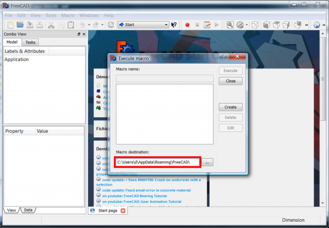
- Aller dans le menu Macro → Macros... ou cliquez sur le bouton
 « Ouvre une boîte de dialogue pour exécuter une macro enregistrée »
- Une boîte de dialogue s'ouvre, indiquant la destination du répertoire Macro
- Sous Windows tel que dans la capture d'écran ci-dessous, l'emplacement est C:\Users\your_user_name\AppData\Roaming\FreeCAD\
- Sous Ubuntu, l'emplacement par défaut est /home/your_user_name/.FreeCAD'
Ici un petit tutoriel How to install macros pour installer une macro
Exemples
Cutting tools
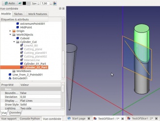
Setting of the Cutting tools: Select an object to cut, a cutting line and a reference Plane.
Angle is an angle between the cutting Plane and the Ref. Plane.
Thickness is the wide of the of the cutting Plane.
Here we have selected a cylinder.
The result will be : the cylinder is then cut in two parts!
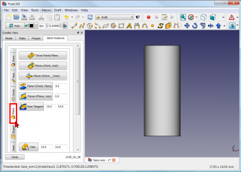
Example the practice
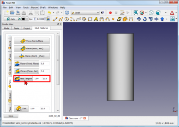
and click the Plane button
(you can change the dimensions of the plane (Default: 10 x 10)).
click you work object. The plane is created tangent of the object (here a cylinder)
click the Tab Modif, and
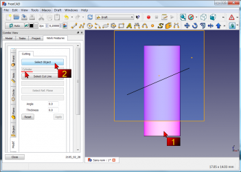
1 : click your object for cutting
2 : click the Select object button (here the cylinder and then name is displayed)
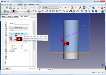
3 : click your line for cutting your cylinder
4 : click the Select Cut Line (then name is displayed)
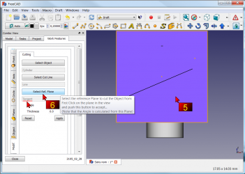
5 : click the work plane
6 : click the Select Ref. Plane button (then name is displayed)
The operation is completed and all operations are preserved.
you can also give Angle and Thickness for your cut.
Concentric constraint between two non cylindrical parts
How to Constraint Between two non cylindrical parts.
1 : The original object to modify.
2 : Objective center two square tubes.
3 : Select the first object and in the menu Axis 1/2 click "Object(s)" X, Y, Z Axes.
4 : Same procedure for the second object.
5 : Click on button Draw style and onto "Wireframe",
6 : for clarify the view.
7 : Select the object to center and his axis created.
8 : Click the button Draft Move
9 : and select the first axis to move on the second axis.
10 : Restore normal view with on button Draw style and onto As is.
11 : Click the first object moved and correct the position with "Combo view > Data > Placement".
12 : Select the object created by WorkFeature (contener axis) and delete it.
13 : The object weshed.
14 : The result.
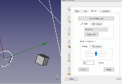
Rotation Object
Click the image for see the animation.
Liens
La discussion sur le forum (en anglais) MACRO:Work Feature 2014_12
Dernière version
Icons :


Sources :
08/03:2105 : WF_2015_03_08
- Circle cut added
- Are Parallel, Are Perpendicular, Are Coplanar added
17/02/2015 : WF_2015_02_17
- Circle and Ellipse Tab added
- Cutting tab added
25/01/2015 : WF_2015_01_25.zip add Object Cylinder Cube
18/01/2015 : WF_2015_01_18.tar.gz add plane and face to view
28/12/2014 : WorkFeatures_2014_12_28.zip
27/12/2014 : WF_2014_12_27.zip
« Ouvre une boîte de dialogue pour exécuter une macro enregistrée »

