|
| Umístění Menu |
|---|
| PartDesign -> Groove |
| Pracovní stoly |
| Návrh dílu, Complete |
| Výchozí zástupce |
| Nikdo |
| Viz také |
| Nikdo |
Úvod
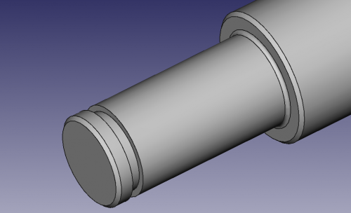
Tento nástroj otáčí náčrtem nebo 2D objektem podle zadané osy a odebírá materiál z podkladu. Například, obrázek ukazuje drážku vyříznutou na hřídeli.
The Groove tool revolves a selected sketch or profile about a given axis, cutting out material from the support .
Above: sketch (A) is revolved around axis (B); resulting groove on solid (C) is shown right.
How to use
- Select the sketch to be revolved.
- v0.17 and above A face on the existing solid can alternatively be used.
- v0.16 and below The sketch must be mapped to the planar face of an existing solid or Part Design feature, or an error message will appear .
- Press the
 Groove button.
 - Set the Groove parameters (see next section).
- Press OK.
Volby
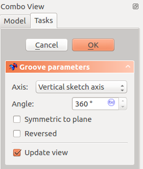
Při vytváření drážky, dialogové okno 'parametry drážky' nabízí několik parametrů, které specifikují jak by se náčrt měl otáčet. Mají stejný význam jako u vlastnosti otáčení.
When creating a groove, the Groove parameters dialogue offers several parameters specifying how the sketch should be revolved.
AxisThis option specifies the axis about which the sketch is to be revolved.
AngleThis controls the angle through which the groove is to be formed, e.g. 360° would be a full, contiguous revolution. It is not possible to specify negative angles (use the Reversed option instead) or angles greater than 360° . Symmetric to planeIf checked, the groove will extend half of the specified angle in both directions from the sketch plane . ReversedIf checked, the direction of revolution is reversed from default clockwise to counterclockwise . |
Properties
Below are properties which can be defined after creation of the feature. Data properties Base and Axis are uneditable .
- DATAAngle: angle of rotation. See Angle .
- DATALabel: label given to the operation, can be changed at convenience.
- DATAMidplane: true or false. See Symmetric to plane.
- DATAReversed: true or false. See Reversed.
- DATARefine: v0.17 and above true or false. If set to true, cleans the solid from residual edges left by features. See Part RefineShape for more details.

