|
| Расположение в меню |
|---|
| PartDesign → Линейный массив |
| Верстаки |
| PartDesign, Complete |
| Быстрые клавиши |
| отсутствуют |
| См. также |
| ... |
Description
The Linear pattern tool creates evenly spaced copies of a feature in a linear direction. Starting with v0.17, it can pattern multiple features.
Above: An L-shaped pad (B) made on top of a base pad (A, also referred to as support) is used for a linear pattern. The result (C) is shown on the right.
How to use
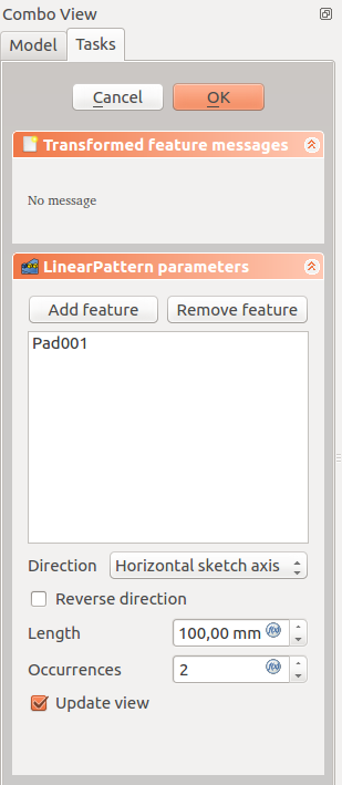
- Select the feature(s) to be patterned. Alternatively, the feature can be selected from a dialogue after step 2.
- v0.16 and below Only a single feature can be selected, and it must be the last one at the bottom of the feature tree.
- Press the
 LinearPattern button.
 - v0.17 and above Press Add feature to add a feature to be patterned. The feature must be visible in the 3D view:
- Switch to the Model tree;
- Select in the tree the feature to be added and press spacebar to make it visible in the 3D view;
- Switch back to the Tasks panel;
- Select the feature in the 3D view; it will be added to the list.
- Repeat to add other features.
- v0.17 and above Press Remove feature to remove a feature from the list, or right-click on the feature in the list and select Remove.
- Define the Direction. See Options.
- Define the Length (distance) between the last copied occurrence and the original feature.
- Set the number of occurrences.
- Press OK .
Options
Direction
When creating a linear pattern feature, the LinearPattern parameters dialogue offers different ways of specifying the pattern direction.
Horizontal sketch axis
Uses the horizontal axis of the sketch for direction.
Vertical sketch axis
Uses the vertical axis of the sketch for direction.
Normal sketch axis
v0.17 and above Uses the normal axis of the sketch for direction.
Select reference...
Allows you to select an edge (such as an edge of the object) to use for direction.
Custom Sketch Axis
If the sketch which defines the feature to be patterned also contains a construction line (or lines), then the drop down list will contain one custom sketch axis for each construction line. The first construction line will be labelled Sketch axis 0.
Base (X/Y/Z) axis
v0.17 and above Select one of the Body Origin's standard axis (X, Y or Z) as direction.
Limitations
- Pattern shapes may not overlap one another except for the special case of only two occurrences (original plus one copy)
- Any pattern shapes that do not overlap the original's support will be excluded. This ensures that a PartDesign feature always consists of a single, connected solid
- For further limitations, see the mirrored feature

