|
| Ubicación en el Menú |
|---|
| Diseño de Piezas-> Simetría |
| Entornos de trabajo |
| Diseño de Piezas, Complete |
| Atajo de teclado por defecto |
| None |
| Ver también |
| None |
Introducción
'Operaciones de simetría' - Esta herramienta toma un conjunto de uno o más operaciones seleccionadas como su entrada (los 'originales'), y produce un segundo conjunto de operaciones simétricas sobre un plano. Por ejemplo:
The Mirrored tool mirrors one feature on a plane. Starting with v0.17, it can mirror multiple features .
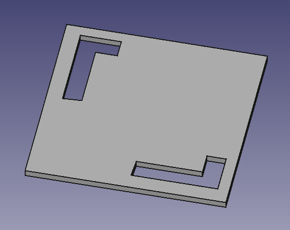
Above: a Pocket feature was created from a sketch containing a circle (A), the Pocket was subsequently used to create a Mirrored feature. The sketch vertical axis (B) was used as axis of symmetry. The result (C) is shown on the right.
Opciones
Cuando se crea una operación de simetría, el letrero de diálogo de 'parámetros de simetría' ofrece dos diferentes modos de especificar el plano de simetría.
Plano estándar
Uno de los planos estándar XY, YZ o XZ se pueden seleccionar con las casillas de selección.
Seleccionar una cara
Presionando el botón 'Plano' permite seleccionar una cara de un sólido pre-existente como plano de simetría. Observa que el botón debe presionarse de nuevo cada vez para seleccionar una nueva cara.
Seleccionar los originales
La lista de los 'originales', muestra las operaciones de las que se hará la simetría. Designando en cualquier operación se añadirá a la lista.
- Select the feature(s) to be mirrored. Alternatively, the feature can be selected from a dialogue after step 2.
- v0.16 and below Only a single feature can be selected, and it must be the last one at the bottom of the feature tree.
- Press the
 Mirrored button.
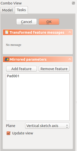
 - v0.17 and above Press Add feature to add a feature to be mirrored. The feature must be visible in the 3D view:
- Switch to the Model tree;
- Select in the tree the feature to be added and press spacebar to make it visible in the 3D view;
- Switch back to the Tasks panel;
- Select the feature in the 3D view; it will be added to the list.
- Repeat to add other features.
- v0.17 and above Press Remove feature to remove a feature from the list, or right-click on the feature in the list and select Remove.
- Define the mirror plane. See Options.
- Press OK.
Options
Plane
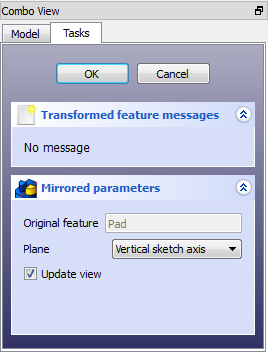
When creating a mirrored feature, the Mirrored parameters dialogue offers different ways of specifying the mirror line or plane .
Horizontal sketch axis
Uses the horizontal axis of the sketch as the axis of symmetry.
Vertical sketch axis
Uses the vertical axis of the sketch as the axis of symmetry.
Select reference...
Allows you to select a plane (such as a face of an object) to use as a mirror plane .
Custom Sketch Axis
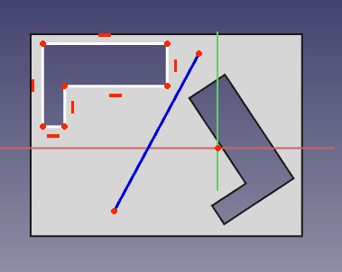
If the sketch which defines the feature to be mirrored also contains a construction line (or lines), then the drop down list will contain one custom sketch axis for each construction line. The first construction line will be labelled 'Sketch axis 0'. The image below is an example with the sketch in edit mode showing that it includes a construction line for use as the Mirrored axis.
Base (XY/XZ/YZ) plane
v0.17 and above Select one of the Body Origin's standard planes (XY, XZ or YZ) .
Preview
The mirror result can be previewed in real time before clicking OK by checking "Update view" .
Limitaciones
- Actualmente, sólo la última operación en el árbol de operaciones se puede seleccionar como el 'original'
- Por tanto, no es posible seleccionar más de una operación para crear la simetría
- Por tanto, no es posible seleccionar más operaciones para añadir a la lista de los 'originales'
- v0.16 and below Only the last feature in the feature tree can be used for the Mirrored feature; therefore,
- it is not possible to choose more than one feature to be mirrored;
- it is not possible to select more features to add to the list view of original features .
- v0.16 and below Once the Mirrored feature has been started or been completed, it is not possible to replace the original feature for a different one .
- The Mirrored feature cannot mirror a whole solid body. For that, see Part Mirror .
- The mirrored feature must intersect the solid (also called support) it is based on, or the command will fail .


