|
| Расположение в меню |
|---|
| PartDesign → Выдавливание |
| Верстаки |
| PartDesign, Complete |
| Быстрые клавиши |
| отсутствуют |
| См. также |
| ... |
Description
The Pad tool extrudes a sketch into a solid in a direction normal to the sketch plane. Starting with v0.17, faces on the solid can also be used.
Sketch (A) shown on the left; end result after pad operation (B) on the right.
v0.16 and below If the selected sketch is mapped to the face of an existing solid or another Part Design feature, the pad will be fused to it.
How to use
- Select the sketch to be padded. In v0.17 and above, a face on the existing solid can alternatively be used.
- Press the
 Pad button.
 - Set the Pad parameters (see next section).
- Click OK.
Options
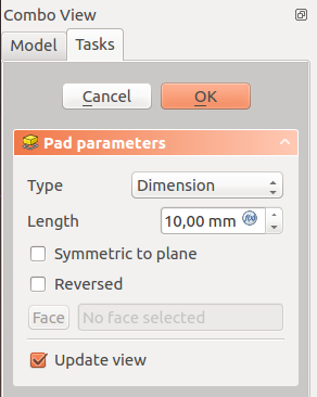
When creating a pad, the Combo view automatically switches to the Tasks pane, showing the Pad parameters dialogue.
Type
Type offers five different ways of specifying the length to which the pad will be extruded.
Dimension
Enter a numeric value for the length of the pad. The default direction for extrusion is away (outside of) the support, but it can be changed by ticking the Reversed option. Extrusions occur normal to the defining sketch plane. With the option Symmetric to plane the pad will extend half of the given length to either side of the sketch plane. Negative dimensions are not possible. Use the Reversed option instead.
Two dimensions
This allows to enter a second length in which the pad should extend in the opposite direction (into the support). Again can be changed by ticking the Reversed option.
To last
The pad will extrude up to the last face of the support in the extrusion direction. If there is no support, an error message will appear.
To first
The pad will extrude up to the first face of the support in the extrusion direction. If there is no support, an error message will appear.
Up to face
The pad will extrude up to a face in the support that can be chosen by clicking on it. If there is no support, no selections will be accepted.
Length
Defines the length of the pad. Multiple units can be used independently of the user's units preferences (m, cm, mm, nm, ft or ', in or ").
Symmetric to plane
Tick the checkbox to extend half of the given length to either side of the sketch plane.
Reversed
Reverses the direction of the pad.
Properties
- DATARefine: v0.17 and above true or false. Cleans up residual edges left after the operation. This property is initially set according to the user's settings (found in Preferences → Part design → General → Model settings). It can be manually changed afterwards. This property will be saved with the FreeCAD document.
Limitations
- Like all Part Design features, Pad creates a solid, thus the sketch must include a closed profile or it will fail with a Failed to validate broken face error. There can be multiple enclosed profiles inside a larger one, provided none intersect each other (for example, a rectangle with two circles inside it).
- The algorithm used for To First and To Last is:
- Create a line through the centre of gravity of the sketch
- Find all faces of the support cut by this line
- Choose the face where the intersection point is nearest/furthest from the sketch
- This means that the face that is found might not always be what you expected. If you run into this problem, use the Up to face type instead, and pick the face you want.
- For the very special case of extrusion to a concave surface, where the sketch is larger than this surface, extrusion will fail. This is a unresolved bug.
- v0.16 and below There is no automatic cleanup, e.g. of adjacent planar surfaces into a single surface. You can fix this manually in the Part workbench with Refine shape (which creates an unlinked, non-parametric solid) or with the Refine shape feature from the OpenSCAD Workbench which creates a parametric feature.
