Contents
Overview
Размещение это как FreeCAD определяет положение и ориентацию объекта в пространстве. Размещение может быть определено в нескольких формах и управляется через скрипты, панель Properties, или диалог Расположение (меню Правка).
Доступ к атрибутам расположения
Доступ и модификация атрибутов расположения объектов может быть получен тремя путями:

Forms of Placement
The placement is stored internally as a position, and a rotation (rotation axis and angle transformed into a quaternion [1]). While there are several forms to specify a rotation, for instance with a rotation center, this is only used to affect the rotation computation and is not stored for later operations. Similarly, if a rotation axis of (1,1,1) is specified, it may be normalized when stored in the quaternion and appear as (0.58, 0.58, 0.58) when browsing the object later.
Angle, Axis and Position
Placement = [Angle, Axis, Position]
The first form of Placement fixes an object's location in space with a Position, and describes its orientation as a single rotation about an axis.
Angle = r is a scalar indicating the amount of rotation of the object about Axis. Entered as degrees, but stored internally as radians.
Axis = (ax,ay,az) is a vector describing an axis of rotation (See Note about axis of rotation). Examples are:
   (1,0,0)       ==> about X axis
   (0,1,0)       ==> about Y axis
   (0,0,1)       ==> about Z axis
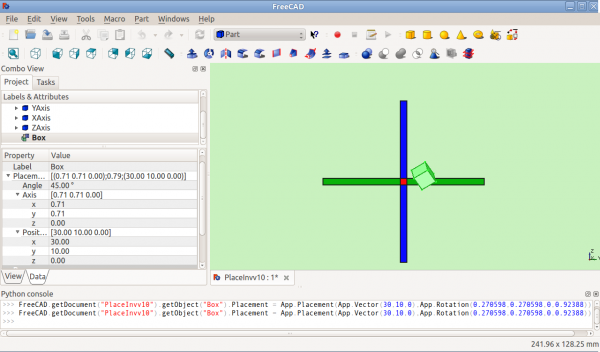
   (0.71,0.71,0) ==> about the line y=x
Position = (x,y,z) is a Vector describing the point from which the object's geometry will be calculated (in effect, a "local origin" for the object). Note that in scripts, Placement.Base is used to denote the Position component of a placement. The Property Editor calls this value "Position" and the Placement dialog calls it "Translation".
Position and Yaw, Pitch and Roll
Placement = [Position, Yaw-Pitch-Roll]
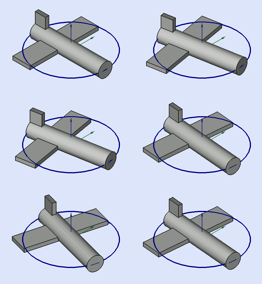
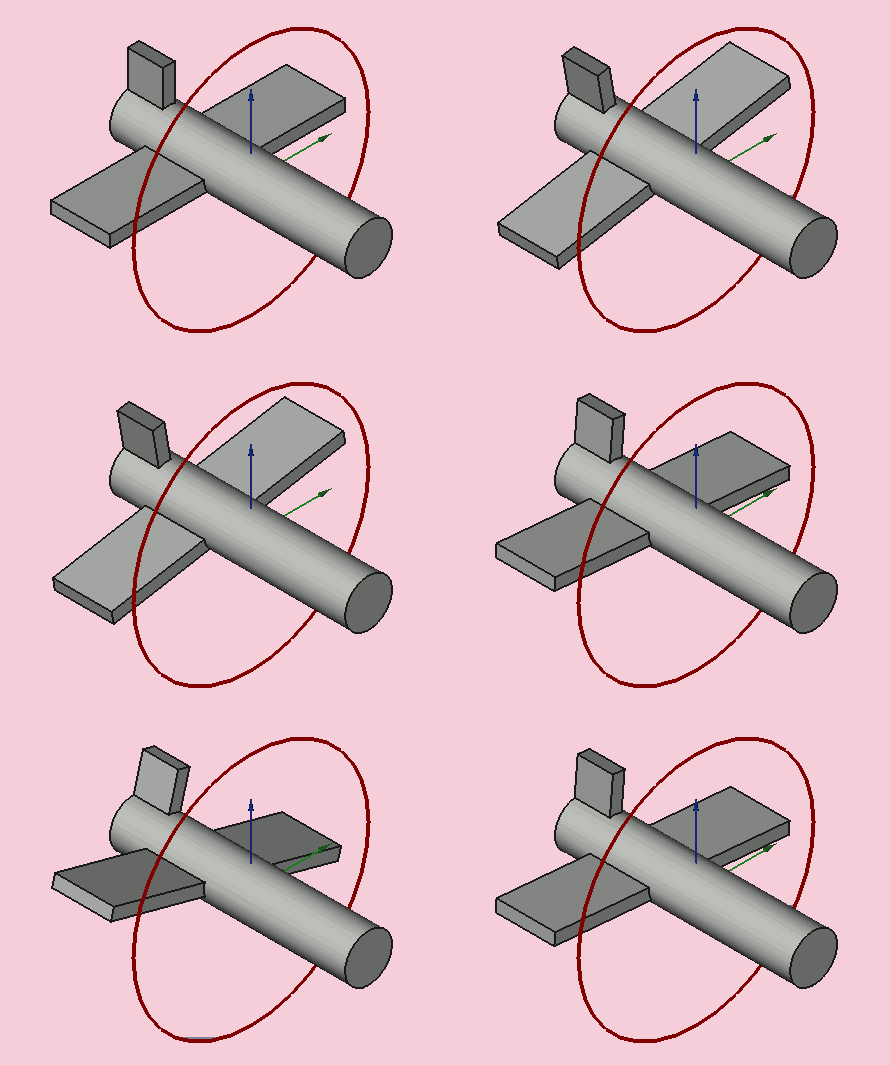
The second form of Placement fixes an object's location in space with a Position (as in the first form), but describes it's orientation using Yaw, Pitch and Roll angles (Yaw, Pitch, Roll). These angles are sometimes referred to as Euler angles or Tait-Bryan angles (Euler angles). Yaw, Pitch and Roll are common aviation terms for a body's orientation (or attitude).
Position = (x,y,z) is a Vector describing the point from which the object's geometry will be calculated (in effect, a "local origin" for the object).
Yaw-Pitch-Roll = (y,p,r) is a tuple that specifies the attitude of the object. Values for y,p,r specify degrees of rotation about each of the z,y,x axis (see note).
>>> App.getDocument("Sans_nom").Cylinder.Placement=App.Placement(App.Vector(0,0,0), App.Rotation(10,20,30), App.Vector(0,0,0))
App.Rotation(10,20,30) = Euler Angle
Yaw = 10 degrees (Z)
Pitch = 20 degrees (Y)
Roll = 30 degrees (X)
(The yaw angle is the Psi ψ).
(The Pitch angle is the Phi φ).
(The Roll angle is the Thêta θ).
Matrix
Placement = Matrix
The third form of Placement describes the object's position and orientation with a 4x4 affine transformation matrix (Affine Transformation).
Matrix =
  ((r11,r12,r13,t1),
   (r21,r22,r23,t2),
   (r31,r32,r33,t3),
   (0,0,0,1)) , with rij specifying rotation and ti specifying translation.
The Placement Dialog
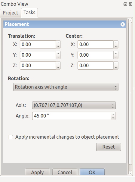
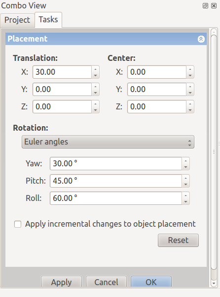
The Placement Dialog is invoked from the Edit menu. It is used to precisely rotate/translate objects. It is also used when we need to create a sketch on a "non standard" plane or change a sketch's orientation to a new plane.
The Translation section adjusts the object's location in space. The Center section adjusts the rotational axis to one that does not pass through the object's reference point. The Rotation section adjusts the rotational angle(s) and the method of specifying those angles.
The Apply incremental changes to object placement tick box is useful when translations/rotations are to be made relative the object's current position/attitude, rather than to the original position/attitude. Ticking this box resets the dialogue input fields to zero, but does not change the object's orientation or location. Subsequent entries do change the orientation/location, but are applied from the object's current position.
PS: since version 0.17 introduce new object Part, this object have his placement, and the Placement object created in the Part object is incremented with the Part Placement. available in version 0.17
For obtain the Part Placement use this code
import Draft, Part
sel = FreeCADGui.Selection.getSelection()
print sel[0].Placement
print sel[0].getGlobalPlacement()   # return the GlobalPlacement
print sel[0].getParentGeoFeatureGroup() # return the GeoFeatureGroup, ex:  Body or a Part.
print  "____________________"
Examples
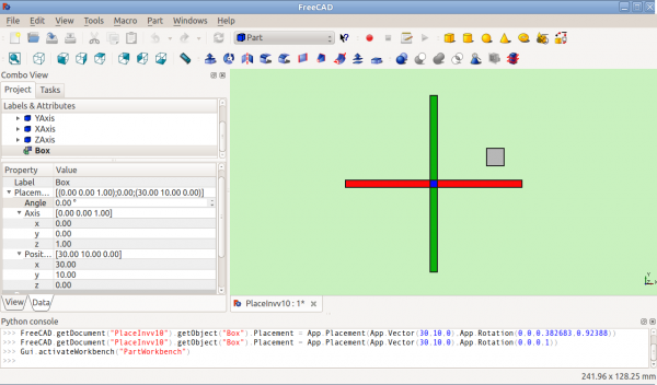
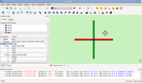
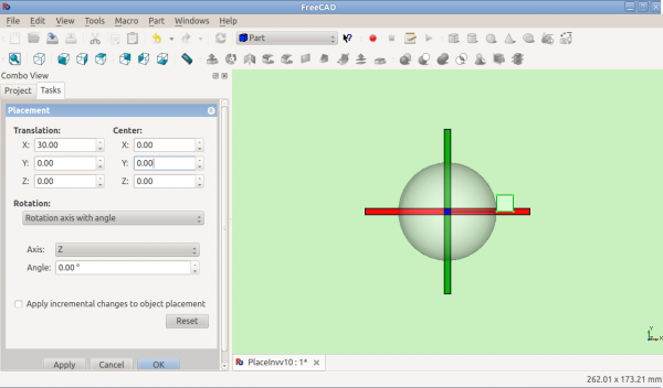
Rotations about a single axis:
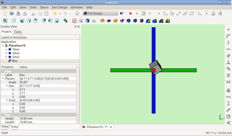
Before Rotation (top view)
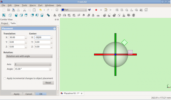
Rotation with offset centre point:
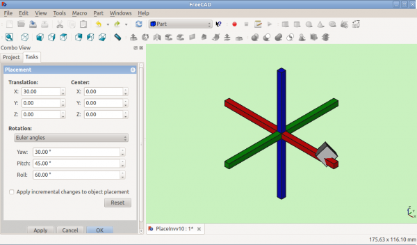
Rotation using Euler angles:
Placement.Base vs Shape Definition
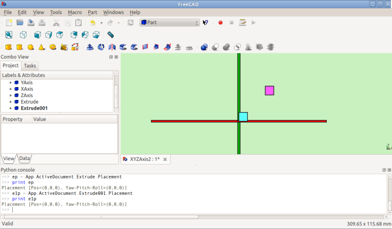
Placement is not the only way to position a shape in space. Note the Python console in this image:
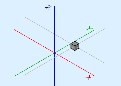
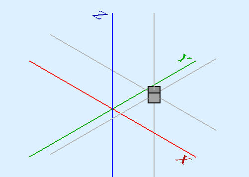
Both cubes have the same value for Placement, but are in different locations! This is
because the 2 shapes are defined by different vertices (curves in more complex shapes). For the 2 shapes in the above illustration:
 >>> ev = App.ActiveDocument.Extrude.Shape.Vertexes
 >>> for v in ev: print v.X,",",v.Y,",",v.Z
 ...
 30.0,30.0,0.0
 30.0,30.0,10.0
 40.0,30.0,0.0
 40.0,30.0,10.0
 40.0,40.0,0.0
 40.0,40.0,10.0
 30.0,40.0,0.0
 30.0,40.0,10.0
 >>> e1v = App.ActiveDocument.Extrude001.Shape.Vertexes
 >>> for v in e1v: print v.X,",",v.Y,",",v.Z
 ...
 0.0,10.0,0.0
 0.0,10.0,10.0
 10.0,10.0,0.0
 10.0,10.0,10.0
 10.0,0.0,0.0
 10.0,0.0,10.0
 0.0,0.0,0.0
 0.0,0.0,10.0
 >>>
The Vertices (or Vectors) that define the shape use the Placement.Base attribute as their origin. So if you want to move a shape 10 units along the X axis, you could add 10 to the X coordinates of all the Vertices or you could set Placement.Base to (10,0,0).
Using "Center" to Control Axis of Rotation
By default, the axis of rotation isn't really the x/y/z axis. It is a line parallel to the selected axis, but passing through the reference point (Placement.Base) of the object to be rotated. This can be changed by using the Center fields in the Placement dialog or, in scripts, by using the Center parameter of the FreeCAD.Placement constructor.
For example, suppose we have a box (below) positioned at (20,20,10).
We wish to spin the box around it's own vertical centre line (ie local Z), while keeping it the same position. We can easily achieve this by specifying a Center value equal to the coordinates of the box's central point (25,25,15).
In a script, we would do:
import FreeCAD
obj = App.ActiveDocument.Box                       # our box
rot = FreeCAD.Rotation(FreeCAD.Vector(0,0,1),45)   # 45° about Z
#rot = FreeCAD.Rotation(FreeCAD.Vector(1,0,1),45)   # 45° about X and 45° about Z
#rot = FreeCAD.Rotation(10,20,30)                   # here example with Euler angle Yaw = 10 degrees (Z), Pitch = 20 degrees (Y), Roll = 30 degrees (X)
centre = FreeCAD.Vector(25,25,15)                  # central point of box
pos = obj.Placement.Base                           # position point of box
newplace = FreeCAD.Placement(pos,rot,centre)       # make a new Placement object
obj.Placement = newplace                           # spin the box
Same script with the file example RotateCoG2.fcstd (discussion on the forum)
import FreeCAD
obj = App.ActiveDocument.Extrude                    # our box
rot = FreeCAD.Rotation(FreeCAD.Vector(0,0,1),45)    # 45 about Z
#rot = FreeCAD.Rotation(FreeCAD.Vector(1,0,1),45)    # 45° about X and 45° about Z
#rot = FreeCAD.Rotation(10,20,30)                    # here example with Euler angle Yaw = 10 degrees (Z), Pitch = 20 degrees (Y), Roll = 30 degrees (X)
centre = FreeCAD.Vector(25,25,0)                    # "centre" of rotation (where local Z cuts XY)
pos = obj.Placement.Base                            # original placement of obj
newplace = FreeCAD.Placement(pos,rot,centre)        # make a new Placement object
obj.Placement = newplace                            # spin the box
Notes
- Axis and Angle can also be expressed as a quaternion.
- The reference point of an object varies depending on the object. Some examples for common objects:
| Object | Reference Point |
|---|---|
| Part.Box | left (minx), front (miny), bottom (minz) vertex |
| Part.Sphere | center of the sphere (ie centre of bounding box) |
| Part.Cylinder | center of the bottom face |
| Part.Cone | center of bottom face (or apex if bottom radius is 0) |
| Part.Torus | center of the torus |
| Features derived from Sketches | the Feature inherits the Position of the underlying Sketch. Sketches always start with Position = (0,0,0). This position corresponds to the origin in the sketch. |
Issues
- As of version 0.13, update of Placement properties in the Data tab has been disabled for objects created with PartDesign, except for the initial sketch from which the solid will be created. Therefore the Placement of a solid created in PartDesign from a sketch can only be altered by adjusting Placement parameters of the initial construction sketch (the first sketch) from which the solid was created.
- Placement functionality will eventually be handled in the Assembly workbench.
More
- This tutorial: Aeroplane covers the mechanics of changing an object's Placement extensively.
- A step-by-step explanation of the Placement Dialog can be found here Tasks_Placement.
