|
| Topic |
|---|
| Whiffle Ball (Part Module) |
| Level |
| Beginner |
| Time to complete |
| Author |
| r-frank |
| FreeCAD version |
| 0.16.6703 |
| Example File(s) |
| [1] Whiffle Ball |
Introduction
This tutorial is here to teach you how to use the Part Module. You will practice:
- inserting primitives
- changing values of primitives
- using placement
- doing boolean operations
Tip: If you selected something wrong or just want to quickly de-select everything,
just click (Navigation-Style OpenInventor: CTRL-Click) in empty space in the 3D-view.
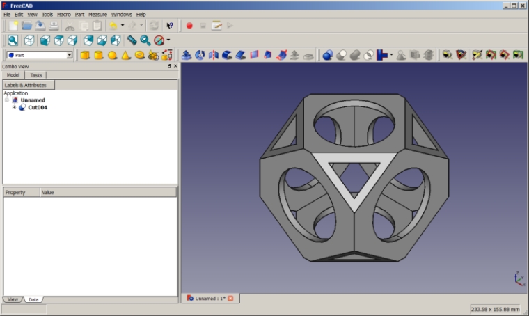
Final model
Setting up the basic shape
- Switch to the Part Module
- Create a new document by clicking on File → New
- Insert box by clicking on

- Make sure the box ("cube") is selected in tree view
- Change the dimensions of the box (see data-tab) to
- Length= 90 mm
- Width= 90 mm
- Heigth= 90 mm
- Click into the value field of placement-row in data-tab so that ... appears on right side
- Click on ... to change the placement of the box
- X: -45 mm
- Y: -45 mm
- Z: -45 mm
- Click on OK to close dialog
- Insert box ("cube001") by clicking on

- Make sure the box ("cube001") is selected in tree view
- Change the dimensions of the box ("cube001") (see data-tab) to
- Length= 80 mm
- Width= 80 mm
- Heigth= 80 mm
- Change the placement of the box ("cube001") to
- X: -40 mm
- Y: -40 mm
- Z: -40 mm
- Click
 to insert a cylinder ("cylinder")
 - Make sure the cylinder ("cylinder") is selected in tree view
- Change radius of cylinder to be 27,5 mm, change height to be 120 mm
- Change placement values of "cylinder" to be
- X: 0 mm
- Y: 0 mm
- Z: -60 mm
- Click
 to insert a cylinder ("cylinder001")
 - Change radius of "cylinder001" to be 27,5 mm, change height to be 120 mm
- Choose Edit > Duplicate selection from the top menu to get another cylinder ("cylinder002")
- Make sure "cylinder001" is selected in tree view
- Change placement values of "cylinder001" to be
- Y: 60 mm
- Rotation axis with angle
- Axis: X
- Angle: 90°
- Click on OK to apply values and close dialog
- Make sure "cylinder002" is selected in tree view
- Change placement values of "cylinder001" to be
- X: -60 mm
- Rotation axis with angle
- Axis: Y
- Angle: 90°
- Click on OK to apply values and close dialog
- Click on
 to change to axometric view
 - Click on
 to zoom to fit all
 - Select "cube001", "cylinder", "cylinder001" and "cylinder002" and fuse them by clicking

- Select "cube" and "fusion", but make sure, that "cube" is selected FIRST
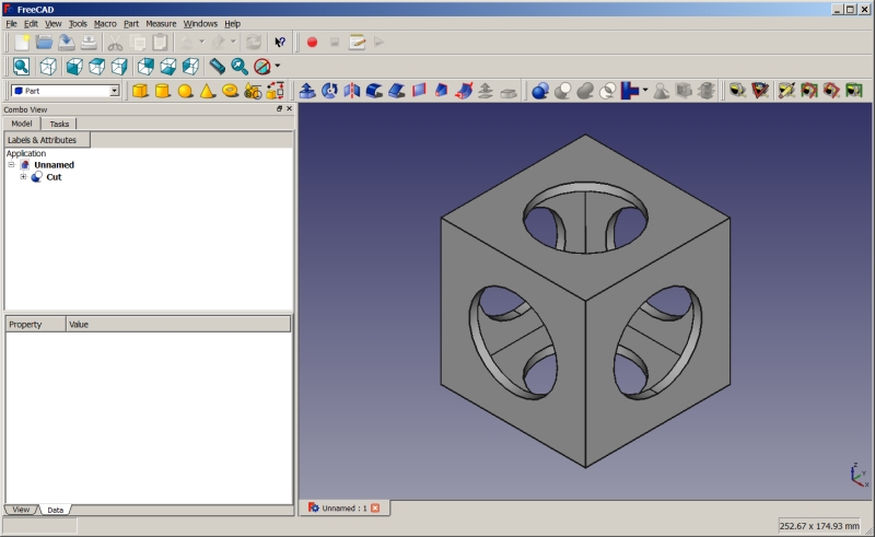
- Apply a boolean cut by clicking

- The finished basic shape should look like this:
Cutting the corners part 1
- Insert box ("cube002") by clicking on

- Change the dimensions of the box ("cube002") (see data-tab) to
- Length= 140 mm
- Width= 112 mm
- Heigth= 112 mm
- Change the placement of the box ("cube002") to
- X: -70 mm
- Y: -56 mm
- Z: -56 mm
- Insert box ("cube003") by clicking on

- Change the dimensions of the box ("cube003") (see data-tab) to
- Length= 180 mm
- Width= 180 mm
- Heigth= 180 mm
- Change the placement of the box ("cube003") to
- X: -90 mm
- Y: -90 mm
- Z: -90 mm
- Make sure "cube002" is selected in tree view, otherwise select it
- Choose Edit > Duplicate selection from the top menu to get another box ("cube004")
- Make sure "cube003" is selected in tree view, otherwise select it
- Choose Edit > Duplicate selection from the top menu to get another box ("cube005")
- Select "cube003" and "cube002", but make sure, that "cube003" is selected FIRST
- Activate menu to change placement
- Tick option "Apply incremental changes to object placement", notice that all values are reset ...
- Choose "Rotation: X-Axis" and "Angle: 45°" and click on Apply
- Choose "Rotation: Z-Axis" and "Angle: 45°" and click on Apply
- Click on OK to close the dialog
- Apply a boolean cut by clicking
 , the resulting object will be named "cut001"
Cutting the corners part 2
- Select "cube005" and "cube004", but make sure, that "cube005" is selected FIRST
- Activate menu to change placement
- Tick option "Apply incremental changes to object placement", notice that all values are resetted ...
- Choose "Rotation: X-Axis" and "Angle: 45°" and click on Apply
- Choose "Rotation: Z-Axis" and "Angle: -45°" and click on Apply
- Click on OK to close the dialog
- Apply a boolean cut by clicking
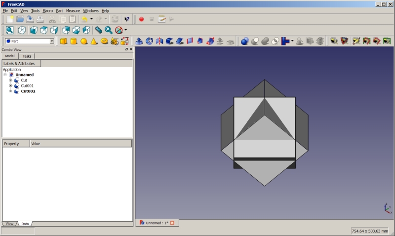
 , the resulting object will be named "cut002"
 - Click on
 to change to axometric view
 - Click on
 to zoom to fit all
If everything went well your model should look like this:
Finishing the model
- Select "cut" and "cut001", but make sure, that "cut" is selected FIRST
- Apply a boolean cut by clicking
 , the resulting object will be named "cut003"
 - Select "cut003" and "cut002", but make sure, that "cut003" is selected FIRST
- Apply a boolean cut by clicking
 , the resulting object will be named "cut004"
 - Click on
 to change to axometric view
 - Click on
 to zoom to fit all
 - Don't forget to save your file ...
Congratulations! You just finished this tutorial succesfully!


