|
| Menu location |
|---|
| Part Design → Create body |
| Workbenches |
| PartDesign |
| Default shortcut |
| None |
| See also |
| Std Part |
Description
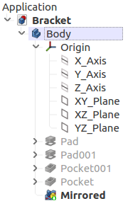
The PartDesign Body contains a series of sketches, datums and PartDesign features that form a single contiguous solid. It provides an Origin (with standard planes and axes) which can be used by the features as references. Furthermore, it can be freely moved as a unit without making it necessary to move the individual features.
Active Status
A FreeCAD document can contain multiple Bodies. Therefore, to add a new feature to a specific Body, it needs to be made active. An active body will be displayed in the tree by a light blue background color.
Activating a Body also automatically switches the interface to the PartDesign workbench, if it was not already the active workbench.
Origin
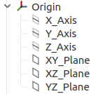
The Origin consists of the three standard axes (X, Y, Z) and three standard planes (XY, XZ and YZ). Sketches can be attached to these planes, and planes along with axes can be used to create other datum (reference) geometry. All elements inside the Body are referenced to the Body's Origin; which means that the body can be moved and rotated in reference to the global coordinate system without affecting the placement of elements inside the body.
Base Feature
The base feature is by definition the first PartDesign feature created in the Body. But it is possible to use a solid shape, either imported or modelled in other workbenches, as a base feature to which sketches and other features can be added.
Tip
The tip is the feature that is exposed outside the Body. It is automatically set to the last feature at the bottom of the tree. But sometimes it can be useful to change it to an earlier feature in the Body tree, which in effect rolls back its history; then it is possible to add features that should have been added earlier. In the Body tree, the feature set to tip displays a green dot with a white down arrow in it.
For more details, see the ![]() Move Tip page.
Move Tip page.
Visibility Management
The Body's visibility supersedes the visibility of any object it contains. If the Body is hidden, the objects it contains will be hidden as well, even if their visibility is set to true. Only one feature can be visible at a time. Selecting a hidden feature and pressing the space bar will make it visible, and automatically hide the previously visible feature.
Interaction with other workbenches
By default, objects underneath a Body are selectable, and this is of course required to edit and add features in PartDesign. But selecting a Body's features to create operations from other workbenches (like Part or Draft) is not advised, as the results may be unexpected; in all cases, an error labelled Links go out of the allowed scope will appear in the Report view.
Therefore, for interactions with other workbenches, only the Body itself should be selected from the Model tree. In cases where it is necessary to select specific topology on the Body (vertex, edge, face), then the Body's Display Mode Body view property can be switched from Through (default) to Tip. This property is accessible from the View panel. In Tip mode, access to the objects under the Body (features, datums, sketches) is disabled; everything but the tip feature will be hidden in the 3D view, no matter which object is set as visible.
Once operations in other workbenches are completed, do not forget to reset the Display Mode Body property to Through to be able to edit the Body.
How to use
- Press the
 Create body button. The new body automatically becomes active.
 - Double-click the Body in the Model tree or right-click and select Toggle active body to activate or deactivate a body.
- If a solid shape is selected first, a BaseFeature solid object is added to the Body; the BaseFeature is linked to the original solid shape. Accepted shapes can be an imported solid, or a solid made in any other FreeCAD workbench.
- In a new document, if a sketch is created from the PartDesign workbench toolbar, a new Body will be automatically created.
Properties
- VIEWDisplay Mode Body: sets the display between two modes:
- Through (default) exposes everything inside the body (features, datums, sketches, etc.). It is the mode used in adding and editing features inside the body.
- Tip exposes only the shape of the Body itself according to the set tip; everything else including sketches is hidden from view and cannot be displayed. Practical use: "Tip" allows selection of edges and faces of the Body to create operations from other workbenches.
- DATATip: displays/sets the feature defined as tip.
- DATABase Feature: displays/sets the external shape used as base feature. Does not apply if a PartDesign feature is the base feature.
- DATAPlacement: specifies the orientation and position of the Body in the 3D space. See Placement.
- DATALabel: the Label is the name given to the operation. This name can be changed at your convenience.
- DATAGroup: lists the referenced objects inside the Body.


