|
| Umístění Menu |
|---|
| Díl -> Vysunutí |
| Pracovní stoly |
| Modul Díl, Kompletace |
| Výchozí zástupce |
| Nikdo |
| Viz také |
Popis
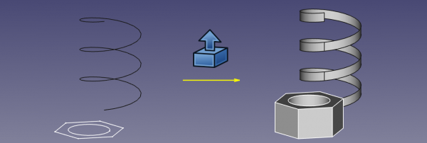
Parametrická vlastnost Vysunutí je dostupná v pracovní ploše Díl z nástrojového pruhu a menu Díl. Vysunutí roztáhne rovinný tvar na definovanou délku podle zadaného směru. Výstupní tvar se změní podle vstupního tvaru a vybraných voleb.
Při standardním scénáři bude očekáván následující seznam požadavků na výstupní tvar z daného vstupního tvaru,
- Vysunutí vrcholu (bodu) vytvoří přímku
- Vysunutí otevřeného okraje (např. čára, oblouk) vytvoří otevřenou plochu
- Vysunutí uzavřeného okraje (např. kružnice) vytvoří volitelně uzavřenou plochu (např. válec s otevřenými konci) nebo, když je nastavena volba "solid (těleso)", vytvoří těleso (např. uzavřené těleso válce)
- Vysunutí otevřeného Drátu (např. nakreslený Drát) vytvoří otevřený plášť (několik spojených ploch)
- Vysunutí uzavřeného Drátu (např. nakreslený Drát) vytvoří buď plášť (několik spojených ploch) nebo, když je nastavena volba "solid(těleso)", bude vytvořeno těleso.
- Vysunutí plochy vytvoří těleso
- Vysunutí Textového řetězece vytvoří složeninu těles (textový řetězec je složenina písmen, z nichž každé je těleso)
How to use
- Select the shape(s) in the 3D view or in the Model tree
- Click on the
 Extrude icon in the toolbar, or go to the Part → Extrude menu
 - Set the direction and length and optionally other parameters (see the following Parameters section for more details).
- Click OK.
Alternatively, the selection can be done after launching the tool, by selecting one or more shape from the list in the Tasks panel.
The Model tree will list as many Extrude objects as there were selected shapes. Each input shape is placed underneath its Extrude object.
Parametry
Parametrický obdélníkový kvádr je definován prametry
- Základna - vstupní tvar (tvar, na který bude vysunutí aplikováno)
- Směr a vzdálenost vysunutí tvaru definované vzdáleností v každé ze tří os X, Y a Z
- Těleso - true nebo false přepíná mezi pláštěm a tělesem
- Úhel zúžení
- Umístění - standardní parametry umístění
- Označení
- Base: the input shape (the shape upon which the Part Extrude was applied)
- Dir: the direction to extend the shape. If Dir Mode is 'Custom', you can edit Dir. Otherwise, Dir is read-only, and computed from the linked shape.
- Dir Link: parametric link to a edge (line) that sets the direction of extrusion. As of v0.17, this property is not supported by property editor.
- Dir Mode: sets how Dir is controlled. 'Custom' meand Dir is editable. 'Edge' means Dir is obtained from an edge (line) linked by Dir Link. 'Normal' means Dir is perpendicular to plane of the input shape.
- Length Fwd: The distance to extrude by. If both Length Fwd and Length Rev are zero, the length of Dir vector is used.
- Length Rev: Additional length to extrude against Dir.
- Solid: if True, extruding a closed edge or a closed wire will yield a solid. If False, a shell will result.
- Reversed: reverses the extrusion to go against Dir.
- Symmetric: if True, extrusion is centered at the input shape, and total length is Length Fwd. Length Rev is ignored.
- Taper Angle and Taper Angle Rev: applies an angle to the extrusion, so that sides of the extrusion are drafted by the specified angle. Positive angle means the cross-section expands. Taper Angle Rev sets the taper for the reversed part of the extrusion (the part from Length Rev). As of v0.17, tapered extrusion is only supported for wires with no holes.
- Face Maker Class: sets C++ class name of face making code, which is used when making solids from wires. This property is here mainly for maintaining backward compatibility. Do not touch, unless you know what you are doing.
- Placement: the standard placement parameters
- Label: label to be shown in the Model tree (not available on Extrude creation)
Task dialog
- OK: creates the extrusion, and closes the dialog.
- Close: closes dialog, without doing anything.
- Apply: creates the extrusion, but does not close the dialog. You can then select another shape in the list on the bottom, and create more extrusions. Clicking Apply may times creates many extrusions.
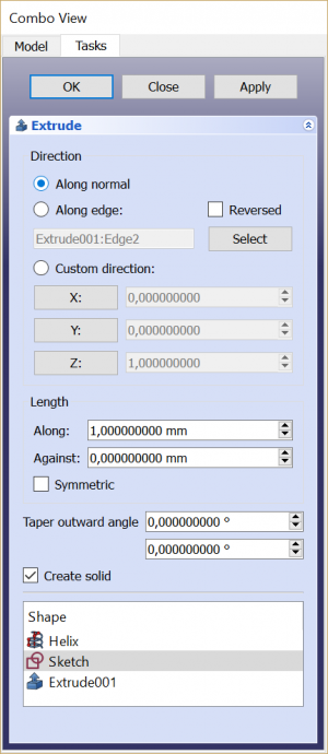
- 'Direction' radio buttons: set the way extrusion direction is computed.
- 'Select' button: click it, and then pick an edge in 3D view. That edge will appear in text field next to the button, in format "ObjectName:EdgeN". You can also type the link manually. Values X,Y,Z will be filled according to the edge direction.
- X, Y, Z buttons: click X button to set extrusion direction to +X axis. Click it again to set -X axis.
- X,Y,Z input fields: set or display the direction vector of extrusion. If both lengths are zero, the length of this vector sets the length of extrusion, and values are always in mm, regardless of unit preferences.
- Length fields: set length of extrusion. These input fields have unit support.
- Symmetric: spreads out the extrusion into both directions, so that the profile remains in the middle.
- Taper Outward Angle: positive angle means profile is expanded at other end of extrusion.
- Create Solid checkbox: if checked, extruding a closed wire or edge will yield a solid. It is checked by default, if a closed wire was preselected before invoking Part Extrude.
- Shape list: here you select, what shapes to extrude. If multiple objects are selected, multiple Extrude objects are created.
Gotchas
Part Extrude dialog does not offer a preview, yet. 'Apply' will create an extrusion object every time you click it, which can be useful as preview; however, they will remain and yet another one will be created as you click OK. Undo can be useful to clean them up before clicking OK.
Since v0.17, a sketch created from within PartDesign cannot be used for Part Extrude, if it is within a Body ("Links go out of allowed scope" error). In order to Part-Extrude a sketch, you should create the sketch from Sketcher workbench. Or you can just drag a PartDesign one out of a Body.
Extrusion with taper angle does not support holes. It also may give bogus results if the number of segments in the profile changes as a result of taper.
Comparison with PartDesign Pad
PartDesign Pad is also an extrusion feature, but there are important differences.
Part Extrude always creates a standalone shape. PartDesign Pad fuses the extrusion result to the rest of the Body.
Part Extrude doesn't care where it is in model tree. PartDesign Pad can only live inside a PartDesign Body.
Part Extrude can extrude any object that has Part Geometry (OCC shape), except for solids and compsolids. And it can't extrude individual faces of other objects. PartDesign Pad will only accept a Sketch as a profile (and a small selection of other object types), or a face of a solid.

